About addVelocity/Pressure Boundary Condition

[size=medium]Hi,

I was trying to set velocity BC in the inlet and the pressure BC in the outlet. In the Cylinder2D.cpp case, I saw the sentences below are used to set the BC.


boundaryCondition.addVelocityBoundary0N(0, 0, 1, ny-1, omega);
boundaryCondition.addPressureBoundary0P(nx-1, nx-1, 1, ny-1, omega);

But I was confused that when I simulate a case needed to use Velocity BC, what I know is the velocity in the inlet, why should I give the omega to the simulation process?Is there any reasons for doing that?

Another question, when I set the pressure BC in the outlet, what I know is the outlet pressure, so I define the outlet Rho as below.


lattice.get( nx-1,iY).defineRho(rho);

Why I need to set the omega in the beginning when add the Pressure BC? If it is necessary, how to adjust the omega, what the relationship between pressure and omega is. What is the effect of omega for the BC? Could you give me some hint?

Thank you in advance.

Regards,

Wei[/size]
Hi,

Omega is the relaxation parameter which is related to the fluid viscosity. Earlier in your code you already assigned this parameter to all bulk cells. When constructing boundary nodes, the value must be re-assigned for structural reasons.

Generally speaking, it is most likely that your value of omega on boundary nodes is equal to the value of omega on bulk nodes.

[size=medium]Hi jlatt,

Your reply is really helpful. Thank you!

Wei[/size]

Hi,

What is the difference between:

a)addPressureBoundary0N
and
b)addPressureBoundary0P

Thanks a lot

Hey Jesantos,
I’m pretty sure I’m misinterpreting your question but:

the N/P is the direction of the normal of the boundary Negative/Positive and the 0 is the axis. 0-> X, 1->Y, 2->Z

Hi @Catsgomeow,

That was exactly the answer I was looking for.
One more question, why in the examples, the inlet typically has N (negative)?
My intuition tells me that I would like the normal to point inside the domain, but I might be wrong.

Hey Jesantos,

Glad I could help !
Normal vectors are usually outward facing as a general rule.
To really understand why you’d have to read more about Divergence theorem and continuity equations !

thanks a lot @Catsgomeow , this is very useful.

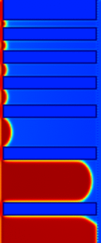
I was wondering if you might now how to do this. I’m modelling 2 fluids using the ShanChen model. For this case, I’m changing the pressure at the boundary to make the fluid (red) flow inside the domain.

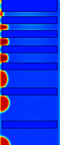
It looks something like this, it’s a bundle of tubes

I achieve this by resetting the density at the boundaries at every iteration:

Array<T, 3> zeroVelocity(0., 0., 0.);
initializeAtEquilibrium(lattice_fluid1, Box3D(1, 2, 1, ny-2, 1, nz-2), rho_fluid1, zeroVelocity);
initializeAtEquilibrium(lattice_fluid2, Box3D(1, 2, 1, ny-2, 1, nz-2), rhoNoFluid, zeroVelocity);
initializeAtEquilibrium(lattice_fluid1, Box3D(nx - 2, nx-1, 1, ny-2, 1, nz-2), rhoNoFluid, zeroVelocity);
initializeAtEquilibrium(lattice_fluid2, Box3D(nx - 2, nx-1, 1, ny-2, 1, nz-2), rho_fluid2, zeroVelocity);

 lattice_fluid1.initialize();
 lattice_fluid2.initialize();

This works well, and it complies reasonable well with the Young-Laplace analytical solution. Nevertheless, I think that using the notation mentioned above would be more elegant, and maybe more efficient.

                    OnLatticeBoundaryCondition3D<T,DESCRIPTOR>* boundaryCondition;

                    Box3D inlet(1, 2, 1, ny-2, 1, nz-2);
                    boundaryCondition->addPressureBoundary0N(inlet, lattice_fluid1);
                    boundaryCondition->addPressureBoundary0N(inlet, lattice_fluid2);
                    setBoundaryDensity(lattice_fluid1, inlet, rho_fluid1);
                    setBoundaryDensity(lattice_fluid2, inlet, rhoNoFluid      );

                    Box3D outlet(nx - 2, nx-1, 1, ny-2, 1, nz-2);
                    boundaryCondition->addPressureBoundary0P(outlet, lattice_fluid1);
                    boundaryCondition->addPressureBoundary0P(outlet, lattice_fluid2);
                    setBoundaryDensity(lattice_fluid1, inlet, rhoNoFluid       );
                    setBoundaryDensity(lattice_fluid2, inlet, rho_fluid2);

                    delete boundaryCondition;

By trying this I get a strange behavior:

Do you know what might be causing this?

Thanks a lot for your time.

Best,
Javier

@jesantos
Hmm I’m not 100% sure just looking at that
I think you’re overwriting the boundary density.
at the inlet you have

setBoundaryDensity(lattice_fluid1, inlet, rho_fluid1);

and at the outlet

setBoundaryDensity(lattice_fluid1, inlet, rhoNoFluid       );

both of these are set on the same domain as you can see below second variable is the domain where the density is set

void plb::setBoundaryDensity<...>(plb::MultiBlockLattice3D<...> &lattice, plb::Box3D domain, T rho)

Thanks a lot for spotting that. Rookie mistake. I’ll replace the second paragraph to outlet.

Thanks again.

Best,
Javier

Very strangely, I keep seeing the same behavior. It is like the fluid is placed at the inlet on the first iteration, and that’s it. Unlike the first picture where is constantly placed at the inlet on every iteration. I even tried erasing the last line (delete boundaryCondition), but I’m still observing the same behavior.

Do you have any intuition on why this might be happening @orestis?
Do you think it is worth to change this in the first place? I feel like there might be benefits, but I’m a little foreign to the Palabos engine.

Thanks @Catsgomeow for your help.

PS: The code is located here: https://github.com/je-santos/MultiphasePorousMediaPalabos/tree/master/examples/validation_YoungLaplace

@jesantos
Hmmm that’s weird ! The only thing I can think of looking very quickly at your code might be that the first iteration is applying due to the PorousMediaSetup function, but the actual boundary conditions haven’t actually been applied. Sorry i can’t be more help !

Hello,
I’m not spotting anything obvious. A thing that seems “strange” (although I don’t think that’s the problem) is that your in/outlets are 2 cells thick. You can make them only one cell think by using

Box3D inlet(1, 1, 1, ny-2, 1, nz-2);

Are you also adding/deleting the BC are every iteration? You should only add them once and then only set the boundary density.

Hello all,
I’m trying to implement an inlet BC for multiphase flow using the twophasemodel in Palabos.
I tried using :

OnLatticeBoundaryCondition3D<T,DESCRIPTOR>* boundaryCondition;
Box3D inlet(1, nx-2, 1, ny-2, nz/12, nz/12);
boundaryCondition->addVelocityBoundary2P(inlet, fields.lattice2);
setBoundaryDensity(fields.lattice2, inlet, rho); >

It didn’t work, I tried also :

OnLatticeBoundaryCondition3D<T,DESCRIPTOR>*
boundaryCondition = createLocalBoundaryCondition3D<T,DESCRIPTOR>();
boundaryCondition->addVelocityBoundary2P(inlet, fields.lattice2);
setBoundaryVelocity(fields.lattice2, inlet, inletVelocity);
applyProcessingFunctional(new InletConstVolumeFraction3D<T,DESCRIPTOR>(1.002), inlet, fields.lattice2); >

But I have problem with “fields.lattice2” as an argument in each of them.
If you have any idea on the source of the problem or a suggestion on how to implement a velocity inlet in such a case/model, I would appreciate it.

Best regards,

Hey @Mehdi.04,

what kind of problem with fields.lattice2 are coming up ?

In the first thing you tried you are setting a velocity boundary and then setting the density which would do nothing I believe ( one of the palabos people please correct me if i’m wrong here)
you should either do

boundaryCondition->addVelocityBoundary2P(inlet, fields.lattice2);
setBoundaryVelocity(fields.lattice2, inlet, vel); >

or

boundaryCondition->addPressureBoundary2P(inlet, fields.lattice2);
setBoundaryDensity(fields.lattice2, inlet, rho); >

also take care that your P and N aren’t reversed

@Catsgomeow Thank you for you answer. Yes I’m sorry, there was a line I deleted by mistake <addPressureBoundary2P(inlet, fields.lattice2)> and when I use one the other one is “commented”.

For the problems I’m getting, either no velocity is applied (no errors during compilation) or an error on the applyproccessingfunctional, which does not recognize the fields.lattice2

@Mehdi.04 hmm hard to say really

from what I can see the first should work if the velocity is in the correct direction and is set with the setBoundaryVelocity

I can’t really comment on the second method you tried i’ve never used that processing functional so i’m worried i’d steer you wrong

Sorry don’t have any solution really…

1 Like

Hello,

what is the problem you are facing exactly? What do you mean by “no velocity is applied”? What is the compilation error?

Hello Orestis, I solved it using

OnLatticeBoundaryCondition3D<T,DESCRIPTOR>* boundaryCondition;
boundaryCondition = createLocalBoundaryCondition3D<T,DESCRIPTOR>();
boundaryCondition->setVelocityConditionOnBlockBoundaries (fields.lattice, bottom, boundary::dirichlet);
setBoundaryVelocity(fields.lattice, bottom, Array<T,3>((T) 0, (T) 0, (T)param.inlet_velocity_LB)); <

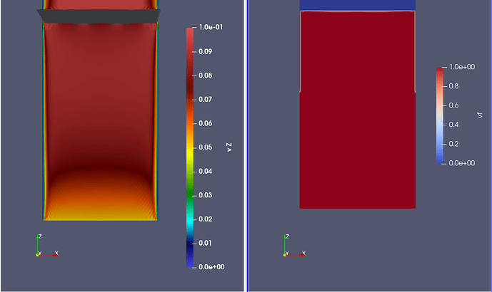
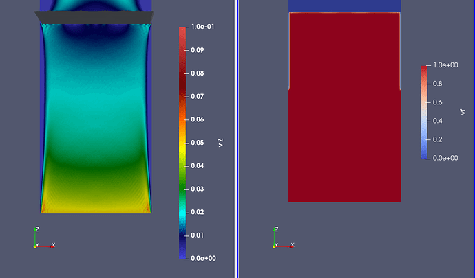
But the flow rate isn’t constant even though the velocity is constant, the velocity keeps oscillating, I don’t know if it’s due to the compressibilty or due to the algorithm that treats the interface.
I’ve put here a picture of the evolution of the velocity, few time steps between the two pictures (It’s periodic, after 800-1000 time steps it does the same)
Also, if you have any recommandations for the theory behind the two phase model, it would really help me.


Best regards,
Mehdi

Hello;
I have some problems with my velocity at two opposite walls. More detail is in this post Free-slip boundary
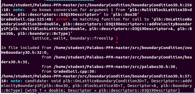
So I tried to change setVelocityonBoundaries to addVelocity, however, when I complied, there is error
image
Could you kindly advice me on this problem ?
Thank you